


Energy Reduction Strategies for Catalytic Reactors – Part1
Catalytic Reaction Processes
A catalytic reactor is a form of a plug flow reactor involving complicated treatment, where the chemical reaction is contained within a vessel. The rate of this reaction is proportional to the number of catalysts the reagents contact, as well as the concentration of the reactants. Another major factor is the inlet temperature of the feed (reagents); this temperature needs to be equal to the activation temperature for the reaction to occur effectively.
To maintain this inlet feed temperature, a heat recovery service known as a feed/effluent exchanger followed by a fired heater preheats the reactor feed to the required inlet temperature. Once the reaction takes place, the effluent of the reactor then enters the feed/effluent exchanger heating the feed entering to the exchanger on the opposite side. The effluent stream is then further cooled by an effluent cooler before it reaches a separator where the liquid product is separated. The vapour component is then recycled via a gas compressor and back into the feed stream to be processed again.
Any excess product in the vapour phase that cannot be compressed is also purged off. The Process Flow Diagram, please refer to Fig 1, illustrates the process. The feed/effluent exchanger is circled in red.
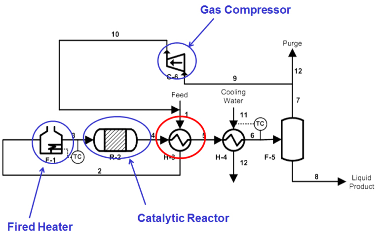
Figure 1
Energy Saving Opportunities
In many processes, there are opportunities to reduce energy and to determine this; a fundamental question needs to be asked; where is the energy consumed within the process? For this particular process, energy is consumed by the fired heater in preheating the feed stream. Also, the gas compressor consumes energy in compressing the gas to recover the pressure loss from the feed stage to the point it reaches the compressor.
There is another piece of plant that may have an indirect influence too, the feed/effluent exchanger. This exchanger is also preheating the feed before the fired heater, and it begs the question if the heat transfer is improved within the exchanger what effect does this have upon the whole process? If there is further heat recovery made by the feed/effluent exchanger, the effects would be:
Reduction in energy needed for the fired heater and as a result, reduction in fuel consumed by the fired heater, saving operating costs.
With a higher inlet temperature sustained through increased heat recovery, this gives margin when the catalyst degrades and will sustain the product quality. With increased product quality, less product will be found in the vapour phase, which reduces the amount being flared off in the purge stream. Overall the process economics are sustained.
With less product in the vapour phase, the energy needed to compress vapour will be reduced, reducing the power consumption of the gas compressor resulting in lower operating costs.
Design challenges for Feed/Effluent Exchangers
With excellent benefits to the process associated with efficient heat recovery, this emphasises efficient design is needed. However, the design is not always straight forward due to a combination of theoretical assumptions being made, and the accuracy of the estimating models for heat transfer and pressure drop in comparison to reality.
Compared to single phase correlations, two-phase heat transfer and pressure drop correlations can have an accuracy of + or – 14%. The accuracy dependency of the physical properties and heat release curve for the process fluids are very important. Assumptions are also made in these correlations on effective mixing of the two phases and uniform flow through the tube bundle when, in reality, this is not always the case. Phase separation and maldistribution can occur within heat exchangers reducing the heat transfer to that of the design estimates.
The impact of fouling upon heat transfer and pressure drop is an additional issue which is difficult to estimate, but none the less it is still very important to gauge. Also, a form of fouling, chemical corrosion of heat exchangers, can occur through reactions taking place between hydrogen and the metal leading to embrittlement. This chemical corrosion can lead to complicated mechanical design and to compensate for increases and wide variations in mechanical design pressures and temperatures, mechanical design is further complicated.
Fundamentally Fig 2 shows the ideal scenario for a temperature cross to provide efficient heat transfer. This re-emphasises the importance of accurate physical properties and heat release curves of process fluids. Many process fluids have non-linear heat release curves, and inaccuracies can assume correct heat flow when, in reality, internal temperature crosses can occur, promoting heat flow reversal.
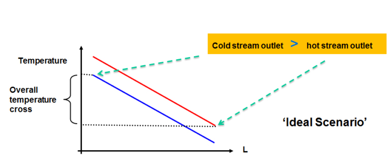
Figure 2
The last design challenge is the fact that the catalyst over time will degrade and compensate for the reduction in performance; the inlet temperature of the feed stream needs to be increased. So when designing feed/effluent exchangers, the heat transfer margin needs to take into account an increasing duty demand over time until the catalyst needs to be replaced, which incurs a substantial expense.
Linked Article
Energy Reduction Strategies for Catalytic Reactors – Part 2 - Design choices of Feed/Effluent Exchangers